Premium Information is available for this item - Upgrade for $1 a day
3020-00-350-6914
Helical Gear
3020003506914 003506914 5638131
A gear, cylindrical in form, with teeth on the outer surface at an angle to the axis of the gear. See also GEAR, ANTIBACKLASH, HELICAL: View more Helical Gear
![]()
January 2023
12


 Marketplace 3020-00-350-6914
Request a Quotation from participating marketplace vendors
 Related Documents 3020-00-350-6914 3+ Documents (More...)
 Restrictions 3020-00-350-6914
3020-00-350-6914 is a Helical Gear that does not have a nuclear hardened feature or any other critical feature such as tolerance, fit restriction or application. Demilitarization of this item has been confirmed and is not currently subject to changes. This item is considered a low risk when released from the control of the Department of Defense. The item may still be subject to the requirements of the Export Administration Regulations (EAR) and the Code of Federal Regulations (CFR). This item is not suspected to be hazardous. The precious metals content of this item is unknown.
 Import and Export 3020-00-350-6914
- Schedule B
- Subscribe to View Schedule B
- HTS Code
- Subscribe to View HTS Code
 End Users 3020-00-350-6914
- Austria (WB01)
- Effective Date:
- 1 Feb 2005
- Greece (ZU01)
- Effective Date:
- 1 Apr 1991
 Approved Sources 3020-00-350-6914
- Part Number
- Manufacturer
- Status
- 5638131
- Manufacturer
- 19207 - U S Army Tank Automotive Command (Active)
- Primary Buy
- Primary Buy
 Datasheet 3020-00-350-6914
- Characteristic
- Specifications
- FIIG
- Specifications
- A27300
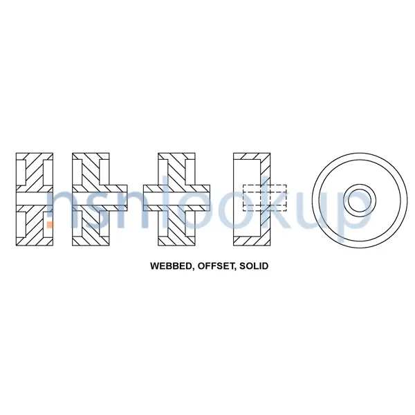
- Body Style [AAQL]
- Webbed, Offset, Solid
- Bore Style [ANTP]
- Involute Spline Both Ends
- Counterbore Nominal Diameter [CWTG]
- 2.8750 Inches Both Ends
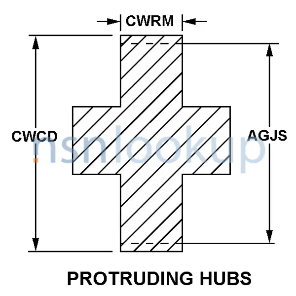
- Face Nominal Width [CWRM]
- 1.875 Inches
- Hardness Rating [CQFM]
- 57.0 Rockwell C Minimum Overall And 63.0 Rockwell C Maximum Overall
- Helix Angle [CWPZ]
- 23.0000 Degrees
- Hub Nominal Diameter [CWTX]
- 3.250 Inches First End
- Hub Style Designator [CWTR]
- Plain First End
- Nominal Distance From Bore Center To Keyway Bottom [CWSR]
- 2.752 Inches Both Ends
- Nominal Distance Between Body Face And Protruding Hub End [CWQL]
- 0.656 Inches Second End
- Nominal Overall Length [CWFR]
- 3.781 Inches
- Nominal Outside Diameter [CWCD]
- 7.581 Inches
- Material [MATT]
- Steel Comp 4320 Overall
- Material Document And Classification [MDCL]
- 66 Fed Std Single Material Response Overall And Aisi/Sae 4320 Assn Std Single Material Response Overall
- Pitch Diameter [AGJS]
- 7.3333 Inches Nominal
- Pressure Angle [CWPP]
- 20.0000 Degrees
- Special Features [FEAT]
- Hub Style Designator Second End Style 10; Spline Minor Dia. 2.415 In.
- Spline Pitch Diameter [BDTX]
- 2.6250 Inches Nominal Both Ends
- Spline Pitch Diameter [BDTX]
- 4.3333 Inches Nominal First End
- Spline Quantity [ABSA]
- 16 Both Ends
- Spline Quantity [ABSA]
- 26 Second End
- Style Designator [STYL]
- Protruding Hubs
- Teeth Quantity [AJLA]
- 44
- Teeth Type [CWMW]
- Single Helix
- Tooth Direction [CWNM]
- Right
- Tooth Form [CWNH]
- Standard
 NATO Stock Numbers Related to 3020-00-350-6914
 Freight Information 3020-00-350-6914
3020-00-350-6914 has freight characteristics.It has a National Motor Freight Classification (NMFC) of 197339. A Sub NMFC of X. It has a NMFC Description of WHEELS COG/GEAR/PINION I/S. 3020-00-350-6914 is rated as class 65 when transported by Less-Than Truckload (LTL) freight. 3020-00-350-6914 is rated as class 60 when transported by Less-Than Carload (LCL) rail or ocean freight. It has a Uniform Freight Classification (UFC) number of 96710 which rates the freight between FCL and LCL. 3020-00-350-6914 has a variance between NMFC and UFC when transported by rail and the description should be consulted. It has a Water Commodity Code (WCC) of 593 for ocean manifesting and military sealift. 3020-00-350-6914 is not classified as a special type of cargo when transported by water. 3020-00-350-6914 is not a consolidation and does not exceed 84" in any dimension. It should be compatible with a standard 72" Aircraft Cargo Door when transported by air.