
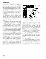

TM 9-2910-226-34 step c (4) above for procedure.) Check condition of fuel control unit and pin (para 3-44). (5) Reduce speed to 1200 rpm and check fuel pressure on gage (A, fig. 3-162) at compensator inlet. Fuel pressure should be 40-55 psi. Adjust droop screw to obtain fuel flow per Table 3-7. (Refer to c (5) and (6) above for procedure.) (6) If fuel flow cannot be adjusted to these limits, check engagement of compensator stop plate, torque link stop and guide, and the angular position of smoke limit torque cam. (Refer to c (6) above for procedure. ) (7) Reduce speed to 700 rpm and check fuel pressure on gage (A, fig. 3-162) at compensator inlet. Fuel pressure should be 30-40 psi. With operating lever in idle position, adjust low-idle adjustment screw (fig. 3-173) to obtain fuel flow per Table 3-7. (Refer to c (7) above for procedure. ) (8) Check 2800 rpm full-fuel flow. If fuel flow does not fall within limits, repeat (2) through (7) above. (9) Reduce test stand rpm to a minimum. When speed reaches minimum, push drive motor stop button (DD, fig. 3-162), and turn speed shifting crank (S) to LOW RANGE. (10) Restart the test stand and adjust speed to 150 rpm, with operating lever in full fuel position. Set count at 1000 and collect fuel in fuel burettes. Fuel flow should be in accordance with Table 3-7. If the fuel flow is below specified limit, the hydraulic head and plunger are worn excessively and the head must be replaced. Replace hydraulic head assembly if proper flow is not obtained, and retest the pump. (11) Activate fuel injection pump electric solenoid fuel shut-off. Apply 24 v dc to solenoid electrical connect ion. Fuel should stop flowing immediately each time the solenoid is activated. If shut -off does not operate, replace solenoid (para 3- 47). (12) Check operating lever travel with tem- plate, 5120-134-7462, as shown in fig. 3-175. Template should be held flush against side of transfer pump with center line mark alined with shaft. Center line of lever must fall within lines indicated. If not within template limits, check governor spacers and springs, gaps and preloads, operating lever to operating shaft position, and smoke limit torque cam angle. If corrections are necessary, fuel flow of pump should be rechecked after any adjustments are made. Figure 3-175. Checking operating lever position (code A pumps). f. Shut-down of Test Stand After Pump Calibration. (Refer to fig. 3-162). Push drive motor stop button (DD) to stop test stand. Turn off the fuel and lube oil heat switches (R and T), the 500.1000- OFF count switch (V), the FORWARD-OFF- Reverse switch (CC), and the auxiliary motor switch (AA). Back off the fuel and lube oil regulators (JJ, HH). Push test stand 24-volt button (P). g. Removal of Pump from Test Stand, (1) Refer to figures 3-163, 3-169 and 3-170, and disconnect and remove the following hoses: (a) Test stand lube pressure-to-fuel injection pump hose (E) to the fuel injection pump oil inlet fitting in the advance housing. - - (b) Fuel injection pump lube return-to-test stand lube return hose (F) to the test stand lube oil return. (c) Test stand fuel pressure-to-supply pump inlet hose (A) to the inlet port of the fuel injection pump fuel supply pump. (d) Fuel injection pump fuel outlet-to- compensator inlet hose (B) to the adapter (J) at the compensator inlet tee (H) (on code G pumps the hose to the hydraulic head). (e) Compensator inlet tee pressure gage hose (C) to the fuel pressure gage (or panel connection). 3-108