
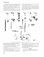

TM 9-2910-226-34 (6) Connect the test stand overflow valve-to- test stand fuel return hose (D) to the injection pump overflow valve. Plug unused opening in tee of overflow valve to prevent loss of test fluid. e. Install nozzle and adapter holders in the ac- cumulator chambers, three on each side of center drive hub (refer to fire 3-164). f. Install previously calibrated nozzle and holder assemblies in the accumulator chambers. Tighten to prevent leakage. (Refer to tables 3-4 through 3-7 for proper nozzles to be used. ) g. Install six fuel delivery tube assemblies supplied with the test stand, to the hydraulic head in correct numbered sequence. (Hydraulic head outlet ports are numbered.) Connect the other end to the injector nozzle assemblies in correct number sequence (fig. 3.171). Figure 3-171. Metering and distributing pump discharge sequence. 3-58. Calibration of Fuel Injection Pump. a. General. The following conditions must be maintained during pump calibration: (1) Fuel pressure in fuel pressure gage (GG, fig. 3-162) must be 3-5 psi, all speeds. (2) Fuel return pressure after overflow valve, 5 psi maximum. (3) Lubricating oil on the lube oil pressure gage (D, fig. 3-162), 35 psi minimum. (4) Do not calibrate pump with diesel fuel heavier than 0.83 specific gravity at 60 degrees F. Heavy and light fuels may be blended to obtain proper specific gravity. (See table 3-9 for specific gravity temperature conversion. ) (5) Final high- and low-idle adjustment to b made on operating engine. (Except on code A pump, adjust low-idle only. ) b. Pre-calibration Procedures. NOTE The key letters shown below in parentheses refer to figure 3-162 unless otherwise in- dicated. 3-104