
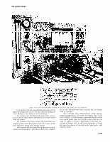

TM 9-2910-226-34 Figure 3-170. Fuel injection pump installed on test stand using panel, part No. 11020519. (1) Connect the test stand lube pressure-to-fuel (J) at the compensator inlet tee (H) (on all except injection pump hose (E) to the fuel injection pump oil code G pumps). inlet fitting in the advance unit housing. (5) Connect the compensator inlet tee-to- (2) Connect the fuel injection pump lube return- pressure gage hose (C) to the fuel gage (fig. 3-163 to-test stand lube return hose (F) to the test stand and 3-169) or to the pressure gage connection of the lube oil return. test stand panel (fig. 3-170) (all except code G). On (3) Connect the test stand fuel pressure-to- code G pumps, install improvised manifold con- supply pump inlet hose (A) to the inlet port of the sisting of elbow (G), tee (H), and adapters (J) and fuel injection pump fuel supply pump. (K) into the elbow of the hydraulic head inlet, and (4) Connect the fuel injection pump fuel supply connect hoses. outlet-to-compensator inlet hose (B) to the adapter 3-103