
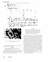

TM 9-2910-226-34 Table 3-7 © Calibration of LDS-465-2 (Code A Pump) Figure 3-168. Aligning scribe mark on timing device hub with timing pointer. b. Slowly actuate the nozzle tester until a pressure reading of 400 psig is attained. NOTE Do not exceed 425 psig as damage to pre- formed packings may result. c. The pressure will drop slowly. When pressure drops to 350 psig, time the rate of pressure drop to 250 psig, If the time of pressure drop from 350 to 250 psig is less than 30 seconds, leakage is indicated. NOTE The time given for test flud at 80 0 F. Test fluid temperature above 80 0 F. will tend to reduce time, while test fluid temperatures below 80 0 F, will tend to increase the time for the pressure to drop to 250 psig. Check for visible external leaks at connections, around the hydraulic head, fuel control unit shaft and plunger drive gear. If no visible external leakage is present, the leakage is internal. Presence of fuel as the fuel control unit indicates a worn fuel control unit shaft, or a damaged control unit packing. Install a new control unit packing (para 3-44) and repeat test. If leakage is still present, install a new fuel control unit (para 3-44). Fuel leakage in the area of the plunger drive gear, as observed through the timing window opening, indicates a damaged hydraulic head, lower ring packing or a worn fuel plunger. Install a new hydraulic head lower ring packing (Para 3-28) and repeat test. If leakage is still present, install a new hydraulic head assembly (para 3-40). An external leak at the bottom of the hydraulic head flange indicates a damaged hydraulic head upper ring packing. Install a new aulic head upper ring packing (para 3-28) and repeat test. d. Install timing device cover and timing window cover or fuel shutoff housing. 3-100 Change 2