
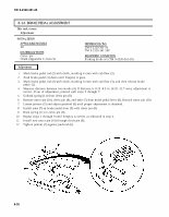

TM 9-2320-361-20 8-14. BRAKE PEDAL ADJUSTMENT This task covers: Adjustment INITIAL SETUP: APPLICABLE MODELS REFERENCES (TM) All TM 9-2320-361-10 MATERIALS/PARTS TM 9-2320-361-20P Cotter pin EQUIPMENT CONDITION Chalk (Appendix C, Item 9) Parking brake set (TM 9-2320-361-10). Adjustment 1. 2. 3. 4. 5. 6. 7. 8. 9. 10. 11. 12. 8-38 Mark brake pedal rod (2) with chalk, marking it even with cab floor (3). Push brake pedal (1) down until freeplay is gone. Mark brake pedal rod (2) with chalk, marking it even with cab floor (3), and then release brake pedal (1). Measure distance between two marks (4). If distance is 0.25 -0.5 in. (6.35 -12.7 mm), adjustment is correct. If out of adjustment, proceed with steps 5 through 7. Unhook spring (11) from clevis pin (8). Remove cotter pin (10), clevis pin (8), and yoke (7) from brake pedal lever (9). Discard cotter pin (10). Loosen jamnut (5) and adjust pushrod (6) until proper adjustment is obtained. Install yoke (7) on brake pedal lever (9) with clevis pin (8). Hook spring (11) to clevis pin (8). Repeat steps 1 through 9 until freeplay is correct as indicated in step 4. Install new cotter pin (10) through clevis pin (8). Tighten jamnut (5) against pushrod (6).