
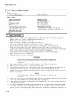

TM 9-2320-361-20 Two 8-12. SERVICE BRAKE BLEEDING This task covers: a. Pressure Tank Method b. Manual Method INITIAL SETUP: APPLICABLE MODELS REFERENCES (TM) All LO 9-2320-209-12-1 MATERIALS/PARTS TM 9-2320-361-10 Hose TM 9-2320-361-20P Screw-assembled lockwasher EQUIPMENT CONDITION Brake fluid (Appendix C, Item 7) Parking brake set (TM 9-2320-361-10). Rags (Appendix C, Item 21) Master cylinder filled (LO 9-2320-209-12-1). PERSONNEL REQUIRED a. Pressure Tank Method 1. 2. 3. 4. 5. 6. 7. 8. 9. 10. 11. 12. 13. 14. 15. 16. 8-32 Remove screw-assembled lockwasher (7) from brace (2) and open access door (1) exposing top of master cylinder (6). Discard screw-assembled lockwasher (7). Disconnect vent line (3) from adapter (4). Clean top of master cylinder (6) and remove filler plug (5). Fill master cylinder (6) with fresh brake fluid to 1/2 in. (1.27 cm) from top. Install adapter plug (9) and male quick-disconnect coupling (8) on master cylinder (6). Make sure brake bleeder tank (10) is charged with brake fluid and is pressurized 20-25 psi (138-172 kPa). Follow manufacturers instructions for purging and preparation before connecting to brake system. Turn flow valve (13) “OFF’ on tank hose (11), if so equipped. Connect female quick-disconnect coupling (12) to male quick-disconnect coupling (8). Turn flow valve (13) “ON’, if so equipped. Check for leaks and correct as necessary. CAUTION Always bleed air-hydraulic cylinder before bleeding downstream hydraulic components. Failure to do so may result in damage to equipment. Clean around bleeder screw (19) located on top front of air-hydraulic cylinder (18). Fill transparent container (17) 1/3 to 1/2 full of brake fluid. Install flexible snug-fitting hose (16) on bleeder screw (19) and immerse other end of hose (15) in transparent container (17). Keep hose (16) end under surface of brake fluid at all times. Loosen bleeder screw (19) 3/4 turn until brake fluid is flowing. Allow brake fluid to flow until no air bubbles are observed. NOTE If brake fluid doesn’t flow after 3/4 turn, go to step 14; otherwise, go to step 15. Turn valve (13) “OFF’ and remove female quick-disconnect coupling (12). Remove and clean bleeder screw (14). Install bleeder screw (19) and repeat steps 7 through 13. Close bleeder screw (19) and remove hose (16) from bleeder screw (19). Tighten bleeder screw (19) 10-20 lb-ft (14-27 NŽm). If hydraulic components of any one wheel were worked on, go to that wheel, clean around bleeder screw (19), and bleed brake system by performing steps 11 through 15. Install end of hose (16) on bleeder screw (15) and immerse other end of hose (16) in brake fluid in transparent container (17).