
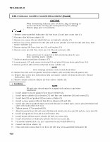

TM 9-2320-361-20 8-10. HYDRAULIC MASTER CYLINDER REPLACEMENT (Contd) CAUTION When disconnecting hydraulic lines and hoses, plug all openings to prevent dirt from entering and causing internal parts damage. Remove plugs prior to installation. 1. Remove screw-assembled lockwasher (6) from brace (2) and open access door (1). 2. Disconect line (4) from adapter (5). 3. Remove two screws (8) and shield (9) from air-hydraulic cylinder (7). 4. Remove two screws (10) from bracket (20) and master cylinder (2). Push bracket (20) away from master cylinder (3). 5. Remove spring (14) from clevis pin (11) and bracket (13). 6. Remove cotter pin (15) from clevis pin (11). Discard cotter pin (15). NOTE Brake pedal must be supported in full extended position for ease when installing master cylinder. 7. Scribe or measure position of jamnut (17). 8. Loosen jamnut (17) and remove clevis pin (11) and yoke (16) from brake pedal lever (12). 9. Remove pushrod (18) and boot (19) from master cylinder (3). NOTE Have drainage container ready to catch brake fluid. 10. Remove line (21) and two gaskets (22) from adapters (23) and (24). Discard gaskets (22). 11. Remove four screws (25), lockwashers (26), and master cylinder (3) from bracket (27). Discard lockwashers (26). 12. Remove adapter (23) and adapter (5) from master cylinder (3). c. Installation NOTE 1. 2. 3. 4. 5. 6. 7. 8. 9. 10. 11. 12. 13. All male pipe threads must be wrapped with antiseize tape before installation. Install adapter (23) and adapter (5) on master cylinder (3). Install master cylinder (3) on bracket (27) with four new lockwshers (26) and screws (25). Install boot (19) and pushrod (18) on master cylinder (3). Install two new gaskets (22) and line (21) on adapters (23) and (24). Install yoke (16) on pushrod (18) to measured distance or scribed mark, ensure yoke (16) forked end alines with brake pedal lever (12). Tighten jamnut (17) on pushrod (18). Aline brake pedal lever (12) with yoke (16) holes and install with clevis pin (11) and new cotter pin (15). Install spring (14) on clevis pin (11) and bracket (13). Install bracket (20) on master cylinder (3) with two screws (10). Install shield (9) on air-hydraulic cylinder (7) with two screws (8). Fill master cylinder (3) 0.5 in. (12.7 mm) from top (LO 9-2320-209-12-1). Connect line (4) on adapter (5). Close and secure access door (1) on brace (2) with new screw-assembled lockwasher (6). 8-28