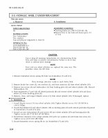
TM 9-2320-361-20 8-9. HYDRAULIC WHEEL CYLINDER REPLACEMENT This task covers: a. Removal b. Installation INITIAL SETUP: APPLICABLE MODELS EQUIPMENT CONDITION All Parking brake set (TM 9-2320-361-10). MATERIALS/PARTS Remove front or rear hubs and drums (para. 9-3 or 9-4). Two lockwashers Two washers Cap and plug set (Appendix C, Item 8) REFERENCES (TM) LO 9-2320-209-12-1 TM 9-2320-361-10 TM 9-2320-361-20P CAUTION Cap or plug all openings immediately stir disconnecting brake lines and hoses to prevent contamination. Failure to do so may result in internal parts damage. NOTE Front and rear wheel cylinders are replaced the same way. This procedure covers the left front. 1. Remove brakeshoe return spring (9) from two brakeshoes (7) and (13). NOTE Have drainage container ready to catch brake fluid. 2. Remove brake line screw (2), two washers (1), and hose connector (3) from wheel cylinder (10). 3. Remove two screws (4) and lockwashers (5) from backing plate (6) and wheel cylinder (10). Discard lockwashers (5). 4. Slide brakeshoes (7) and (13) off slotted pushrods (8) and remove wheel cylinder (10) and dust- shield (12) from backing plate (6). 5. Remove, clean, and inspect bleeder screw (11) from wheel cylinder (10). If damaged, replace. b. Installation 1. Install bleeder screw (11) into wheel cylinder (10). Tighten bleeder screw (11) 120-168 lb-in. (14-19 NŽm). 2. Install dustshield (12) and wheel cylinder (10) on backing plate (6) with slotted pushrods (8) placed in brakeshoes (7) and (13) slots. 3. Install two new lockwashers (5) and screws (4) into wheel cylinder (10) and backing plate (6). Tighten screws (4) 27-35 lb-ft (37-48 NŽm). 4. Install hose connector (3) to wheel cylinder (10) with two washers (1) and brake line screw (2). Tighten screw (2) 65 lb-ft (88 NŽm). 5. Install brakeshoe return spring (9) on two brakeshoes (7) and (13). 8-24

