
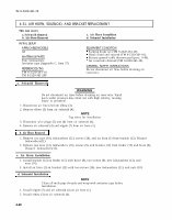

TM 9-2320-361-20 4-31. AIR HORN, SOLENOID, AND BRACKET REPLACEMENT This task covers: a. Solenoid Removal c. Air Horn Installtion b. Air Horn Removal d. Solenoid Installation INITIAL SETUP: APPLICABLE MODELS All MATERIALS/PARTS Four lockwashers Antiseize tape (Appendix C, Item 27) REFERENCES (TM) TM 9-2320-361-10 TM 9-2320-361-20P EQUIPMENT CONDITION Parking brake set (TM 9-2320-361-10). Hood raised and secured (TM 9-2320-361-10). Battery ground cable disconnected (para. 4-48). Air reservoirs drained (TM 9-2320-361-10). GENERAL SAFETY INSTRUCTIONS Do not disconnect air lines before draining air reservoirs. a. Solenoid Removal WARNING Do not disconnect air lines before draining air reservoirs. Small parts under pressure may shoot out with high velocity, causing injury to personnel. 1. Disconnect air line (2) from elbow (3). 2. Remove elbow (3) from air solenoid (4). NOTE Tag wires for installation. 3. Disconnect wire plugs (5) and (6) from air solenoid (4). 4. Remove air solenoid (4) and nipple (7) from air horn (1). b. Air Horn Removal 1. Remove two nuts (10), lockwashers (11), screws (16), and air horn (1) from bracket (12). Discard lockwashers(11). 2. Remove two nuts (14), lockwashers (13), screws (9), and bracket (12) from fender (15) and brace (8). Discard lockwashers(13). c. Air Horn Installation 1. Install bracket (12) on fender (15) with brace (8), two screws (9), new lockwashers (13), and nuts (14). 2. Install air horn (1) on bracket (12) with two screws (16), new lockwashers (11), and nuts (10). d. Solenoid Installation NOTE Clean all male pipe threads and wrap with antiseize tape before installation. 1. Install nipple (7) and air solenoid (4) on air horn (1). 2. Install elbow (3) on air solenoid (4). 4-48