
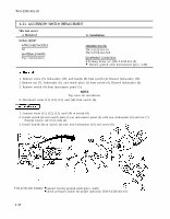

TM 9-2320-361-20 4-21. ACCESSORY SWITCH REPLACEMENT This task covers: a. Removal b. Installation INITIAL SETUP: APPLICABLE MODELS REFERENCES (TM) All TM 9-2320-361-10 MATERIALS/PARTS Two lockwashers TM 9-2320-361-20P EQUIPMENT CONDITION Ž Parking brake set (TM 9-2320-361-10). Battery ground cable disconnected (para. 4-48). 1. Remove screw (9), lockwasher (10), and handle (8) from switch (4). Discard lockwasher (10). 2. Remove nut (7), lockwasher (6), and switch plate (1) from switch (4). Discard lockwasher (6). 3. Remove switch (4) from instrument panel (5). NOTE Tag wires for installation. 4. Disconnect wires (11), (12), (13), and (14) from switch (4). 1. Connect wires (11), (12), (13), and (14) to switch (4). 2. Install switch (4) and switch plate (1) on instrument panel (5) with new lockwasher (6) and nut (7). Position locator tab (3) in hole (2). 3. Install handle (8) on switch (4) with new lockwasher (10) and screw (9). FOLLOW-ON TASKS: Connect battery ground cable (para. 4-48). Check accessory switch for proper operation (TM 9-2320-361-10). 4-36