
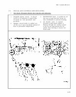

TM 9-2320-209-10-1 4-4. SPECIAL KITS CONTROLS AND INDICATORS. a. Hot Water Personnel Heater Kit Controls and Indicators. 1. HEATER blower switch. Is placed 3. DEFROSTER knob. Is pulled out all in HI or LO position to control flow the way to send the flow of hot air of forced air into personnel com- onto windshield to prevent frosting. partment. 4. Air bleeder valve. Is opened 2. Damper control knob. Is pulled out (turned to left) while coolant is all the way to give maximum amount of flowing through the cooling system heat to personnel compartment. to let air out and prevent an air pocket from forming in heater hot water tank. 4-23