
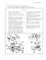

TM 9-2320-209-10-1 4-3. EQUIPMENT BODY CONTROLS AND INDICATORS. a. Fuel Tank Trucks (M49A1C and M49A2C) Controls and Indicators. 1. 2. 3. 4. 5. 6. M49A1C Meter. Records amount (no. of 7. gallons) of fuel pumped out. Counter control lever. Is moved up or down to return numbers on meter 8. to zero. Pressure gage. Shows condition of filter elements by showing differ- 9. ence in pressure between inlet and outlet side of filter. Pressure gage handle. Is turned to No. 1 position (right) to take pressure 10. readings on inlet side of valve. Is turned to No. 3 position (left) to take readings on outlet side of valve. 11. Dump valve control (l-inch line). Is turned left to open automatic dump valve, which dumps water separated from fuel by filter segregator unit. Manual drain valve control (l/2-inch line). Is turned left to open manual drain valve to drain sump assembly. Gravity delivery line gate valve. Is turned left to let fuel flow through gravity delivery line. Pump delivery line gate valve. Is turned left to let fuel flow through pump and dispenser line. Discharge valve control levers. Are pulled back to open discharge valves which control flow of fuel from tank sections. Liquid level gage. Is dipped into tank sections to measure liquid level. Remote control handle. Is pulled forward in an emergency to trip operating levers and return them to the closed position. 4-11