
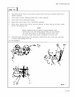

TM 9-2320-209-10-1 1. Pull feed control lever (1) and drive control lever (2) back and place latch (3) in locked position. 2. Place power leveler shifting handle (4) in down position. 3. Place latch (3) in unlocked position. 4. Keep feed control lever (1) in NEUTRAL position. 5. Place drive control lever (2) in forward position to lower derrick (5) into cradle (6) on cab protector (7). NOTE Before locking latch (3) against boring machine feed control lever (1) and drive control lever (2), let machine run with both levers in NEUTRAL position. This will let heat escape from brake assemblies in clutch case. 6. Pull both feed control lever (1) and drive control lever (2) to the rear and lock in place with locking latch (3). GO TO FRAME 9 4-359